


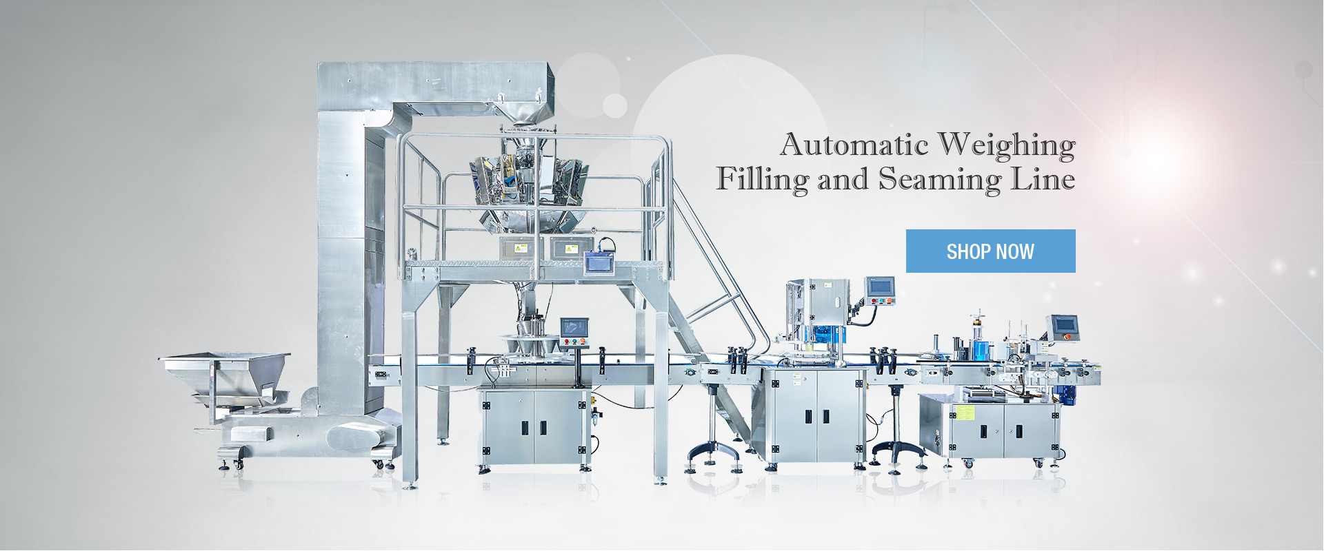




A bottle packaging line does not achieve stable output simply because every machine has a high rated speed. Filling, bottle transfer, accumulation, cap supply, capping, inspection, labeling, and packing must work as one connected system. If one section cannot keep pace with the others, bottles may accumulate, the capping station may run empty, or downstream equipment may create repeated stops.
This guide explains how to evaluate the relationship between filler speed and screw capping capacity. It is intended for packaging engineers, production managers, line integrators, and buyers planning a new bottle line or reviewing why an existing line does not reach its expected output. The goal is not to make every station run at the same displayed number. The goal is to create a stable, manageable flow that protects bottle handling and closure quality.
Why Rated Machine Speed Does Not Equal Line Output
Machine speed is usually stated as bottles per hour, bottles per minute, or cycles per minute. That figure is useful, but it does not describe the total behavior of a packaging line. A filler may be capable of a certain output under ideal conditions, while the capping section may lose time because of cap replenishment, bottle instability, format changes, or downstream interruptions.
Actual line output is determined by the slowest effective stage after normal operating losses are considered. A line may have a fast filler and a fast capper but still underperform if bottles arrive at the capping zone unevenly, if the cap supply cannot recover after short interruptions, or if labels and packing operations create back pressure after capping.
For planning purposes, teams should distinguish between rated capacity and effective capacity. Rated capacity is the stated performance of a machine under specified conditions. Effective capacity is what the station can sustain with the actual product, bottle, cap, operator routine, changeovers, and normal production disturbances.
Map The Full Bottle Flow Before Selecting Capacity
Before deciding whether the capping section is large enough, map the complete path of a bottle from filling to the final downstream process. The map should include transfer points, conveyor curves, sensors, accumulation zones, cap supply locations, inspection stations, and any manual intervention points.
This exercise often shows that the most important limitation is not the capping heads themselves. A narrow conveyor transition, unstable bottle spacing, a short cap buffer, or a downstream labeler that stops frequently can reduce the usable output of the entire line.
| Line Section | Primary Function | Information to Confirm | Common Mismatch | Possible Production Effect |
|---|---|---|---|---|
| Filling machine | Fills product into bottles | Normal output, bottle spacing, discharge pattern | Uneven bottle release | Gaps or crowding before capping |
| Transfer conveyor | Moves bottles between stations | Speed, rail setting, bottle stability, curves | Incorrect guide rail position | Bottle tipping, rubbing, or inconsistent spacing |
| Accumulation area | Absorbs short interruptions | Usable length, bottle pitch, pressure condition | Too little or uncontrolled accumulation | Line starvation or excessive back pressure |
| Cap supply | Delivers caps to the capping station | Supply rate, cap orientation, replenishment process | Cap delivery slower than capping demand | Empty capping station or frequent stops |
| Capping station | Applies and tightens closures | Effective speed, bottle clamping, torque setting | Capacity selected without line data | Capper becomes the system bottleneck |
| Downstream equipment | Inspects, labels, packs, or handles finished bottles | Stop frequency, discharge behavior, recovery speed | Downstream station cannot accept output | Back pressure reaches the capping zone |
Line balancing should be considered alongside bottle format, cap type, torque requirements, and expected changeover frequency. For a broader equipment-selection checklist, see the capping machine decision framework.
Identify The True Constraint
A constraint is the part of a process that limits the overall system’s ability to produce more output. In a bottle line, the constraint can move. During one shift, it may be the filler because product supply is unstable. During another, it may be cap feeding because a cap lot behaves differently. After a format change, conveyor settings or labeler recovery time may become the limiting condition.
Instead of assuming the slowest rated machine is always the bottleneck, review actual production data and direct observations. Track stoppages, short stops, queues, empty conveyor sections, cap shortages, bottle jams, and rework. The station that repeatedly causes the rest of the line to wait is usually the place that deserves attention first.
Record the normal operating rate of each station, not only the maximum rated rate.
Identify where bottles regularly queue or where conveyor sections become empty.
Separate planned stops, such as format changes, from unplanned short interruptions.
Review whether the capper waits for bottles or whether bottles wait for the capper.
Check whether downstream stops travel backward into the capping zone.
Production teams should also avoid trying to solve every issue by increasing conveyor speed. Faster transfer can create new problems if bottle spacing becomes unstable, containers touch each other, or the bottle format is sensitive to vibration and back pressure. Flow control must suit the actual bottle geometry and production conditions.
Match Filling Output To Capping Capacity
The capping station should normally have enough effective capacity to receive the output of the filling section without becoming the routine bottleneck. However, this does not mean the capper must always operate at the highest possible speed. A small amount of planned capacity margin can help a capping station recover from normal short interruptions, but excessive speed difference can create unstable bottle flow or unnecessary mechanical stress.
When comparing filling and capping capacity, use the same unit of measure. If one machine is stated in bottles per hour and another in bottles per minute, convert both values before making a comparison. Then consider the expected operating efficiency, not just the nameplate rating.
A useful planning discussion includes the following questions:
What output is required during a normal production shift?
What output can the filler sustain with the actual product viscosity and fill volume?
What output can the capping section sustain with the actual cap and bottle combination?
How long does cap replenishment or format adjustment take?
How often do downstream labeling or packing sections stop?
Does the line have enough accumulation to absorb routine micro-stops?
Use Accumulation To Absorb Short Disturbances
Accumulation is the controlled storage of bottles between stations. It can help a line continue operating through short stops, but it is not a substitute for correcting persistent equipment problems. The purpose of an accumulation zone is to create time separation between upstream and downstream events.
For example, if a downstream machine pauses briefly, an accumulation area after the capping station may allow the capper to continue for a limited period. If the filler pauses briefly, an accumulation area before the capper may allow the capping section to keep operating while it waits for bottle flow to recover. The appropriate location depends on which equipment is most critical and which interruptions occur most often.
The amount of usable accumulation depends on bottle diameter, bottle pitch, conveyor layout, bottle stability, guide rails, and whether the containers can safely experience back pressure. Tall, lightweight, tapered, or irregular bottles may require more careful accumulation design than short, rigid, stable containers.
Flow Diagram For Filling And Capping Line Balancing
Workflow: Filling machine → Bottle discharge control → Conveyor spacing → Upstream accumulation → Cap supply → Screw capping station → Downstream accumulation → Inspection → Labeling or packing
Each transfer point in this flow should be reviewed during commissioning and during format changes. A line may be stable with one bottle format and unstable with another because bottle geometry, center of gravity, cap dimensions, or required guide rail settings have changed.
Cap Supply Must Match Capping Demand
Cap supply is often treated as a separate system, but it directly affects capping capacity. A capping station cannot maintain its output if caps arrive inconsistently, if cap orientation is unstable, or if replenishment interrupts the feed path. The cap supply system should be reviewed using the actual cap size, cap material, surface condition, and required operating rate.
When a packaging line uses automated cap handling, the supply rate should be evaluated not only during steady operation but also during recovery after a short stop. If the capper resumes faster than the feeder can restore a stable cap flow, repeated interruptions can occur even though both systems appear adequate when measured separately.
Design Checks For A Double-Head Capping Station
A double-head configuration can be considered when the required output exceeds the sustainable capacity of a single-head arrangement or when a line needs more recovery capability after routine interruptions. The decision should be based on the complete line condition, not only on a target bottles-per-hour figure.
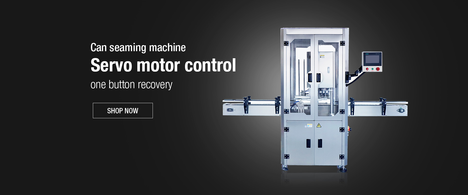
For projects requiring increased capping capacity, a double-head screw capping machine can be evaluated with the bottle format, cap supply condition, conveyor layout, bottle clamping requirement, and target output. Two capping heads do not automatically solve problems caused by poor bottle spacing, unstable cap delivery, or downstream back pressure.
| Planning Check | Why It Matters | What To Review |
|---|---|---|
| Filler output | Determines bottle arrival rate | Actual sustained speed, bottle discharge pattern, product-related slowdowns |
| Cap supply capacity | Determines whether both heads can remain supplied | Cap orientation, feed recovery, refill procedure, cap path stability |
| Bottle handling | Supports consistent cap placement and tightening | Guide rails, clamping, bottle spacing, conveyor transitions |
| Torque control | Protects closure consistency as output increases | Package-specific torque requirements and verification method |
| Downstream capacity | Prevents capping output from creating backup | Inspection, labeling, packing, discharge, and recovery speed |
Head count should be evaluated after confirming the available filler output, cap supply rate, bottle stability, and downstream capacity. The upcoming single versus double head capper comparison explains when a second capping head is likely to improve usable line capacity and when it may simply move the bottleneck to another station.
Illustrative Planning Scenario
A production team plans to increase output on a condiment bottle line. The filler can deliver bottles at a higher rate than the existing capping section can consistently handle, but the line also experiences short labeling stops and periodic cap replenishment.
Planning Challenge: Installing a higher-capacity capping station alone could move the bottleneck to the cap supply or labeling section. If bottles accumulate without adequate control, the new capping station may receive inconsistent bottle spacing or experience downstream back pressure.
Engineering Review: The team maps the line, records sustained output at each station, measures the available accumulation area, checks bottle stability at conveyor transitions, and reviews cap supply recovery after replenishment. The target capping configuration is then evaluated against the full line rather than against filler speed alone.
Expected Result: The planning process identifies where speed margin, conveyor adjustment, cap supply capacity, or downstream recovery is needed before equipment changes are finalized. This is an illustrative engineering scenario, not a published customer case.
Use Torque Data With Line-Speed Data
Line balancing and closure quality should be reviewed together. A capping station may reach a higher output rate while torque variation becomes wider because bottle clamping, cap placement, or line timing is no longer stable. The correct production rate is therefore the speed at which the system can maintain both output and approved closure performance.
For a more detailed approach to verifying closure results after capping, see the screw cap torque testing guide. That article explains why application torque, removal torque, sampling conditions, and recorded operating context should be reviewed as part of the packaging process.
Frequently Asked Questions
Should the capping station run faster than the filler?
In many lines, the capping station needs enough capacity margin to recover from normal short interruptions. The correct margin depends on bottle flow, cap supply, accumulation capacity, changeover frequency, and downstream performance.
How much accumulation is needed before a capping station?
The required accumulation depends on bottle dimensions, conveyor layout, target output, expected short stops, and whether the bottles can tolerate back pressure. It should be calculated and verified using the actual container format.
Why does the capping station sometimes run empty?
Common causes include filler interruptions, insufficient upstream accumulation, unstable bottle discharge, conveyor spacing problems, or a transfer point that cannot maintain bottle flow.
Can cap supply limit total line output?
Yes. If caps are not oriented, delivered, or replenished at a rate that supports capping demand, the capping station can become idle even when bottles are available.
Will a faster conveyor always improve output?
No. Excessive conveyor speed can create bottle instability, poor spacing, contact between containers, and increased back pressure. Conveyor speed should support stable transfer, not only faster movement.
What should be checked before upgrading to a double-head capping system?
Check filler output, cap supply capacity, bottle stability, conveyor layout, accumulation capacity, torque-verification requirements, downstream equipment capacity, and the expected frequency of format changes.
Why GZFHarvest Is Relevant to Bottle Line Integration
Guangzhou Full Harvest Industries Co., Ltd. supplies packaging machinery for bottle and can production lines, including filling, sealing, screw capping, and labeling equipment. For integrated bottle line projects, the company can review container dimensions, cap format, required output, and equipment connection requirements so that filling, conveying, capping, and downstream handling are considered as related production steps.
Authoritative Sources
Line Balancing in Food Supplement Packing Process Using Simulation Program
https://ph02.tci-thaijo.org/index.php/TJOR/article/view/258991
A computer simulation case study of Productivity Improvement for Kaoliang Spirits Factory in China
https://www.kci.go.kr/kciportal/ci/sereArticleSearch/ciSereArtiView.kci?sereArticleSearchBean.artiId=ART001703020
Optimising material flow through virtual prototyping
http://icmas.eu/Volume20_Issue4_2025.htm


